For Doctors Proximal Humeral Fractures, Extra AArticular 2-Part, Surgical Neck, Impaction Treatment ORIF - Plate fixation
1. Principles
Disimpaction
Disimpaction is the key to successful reduction of these fractures.
Proper reduction
After reduction, alignment should be correct in both sagittal and coronal planes. Rotational alignment must also be correct.
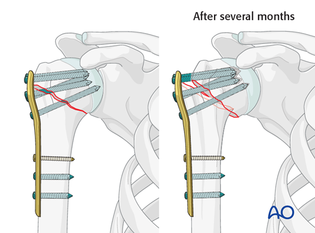
Restore normal valgus alignment by reducing the humeral head against the plate. Incarceration of the biceps tendon in the fracture may prevent reduction.
Correct plate position
A correct plate position must be ensured in order to avoid loss of reduction and impingement.
Angular stable versus standard plates
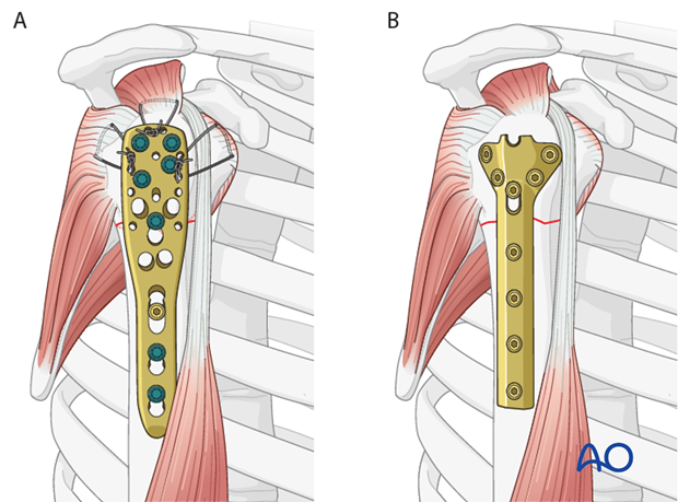
This procedure describes proximal humeral fracture fixation with an angular stable plate (A). Sometimes, these implants are not available. Standard plates provide an alternative option, for example the modified cloverleaf plate (B). Presently, the specific indications, advantages, and disadvantages of angular stable and standard plates are being clarified. There is some evidence that angular stable plate provide better outcomes. In addition to type and technique of fixation, the quality of reduction, the soft-tissue handling, and the characteristics of the injury and patient significantly influence the results. There is no evidence that the use of angular stable plates will overcome these other factors.
2. Patient preparation and approaches
Patient preparation
It is recommended to perform this procedure with the patient in a supine position (with the beach chair position as alternative).
Approaches
The deltopectoral approach provides safe and good access to the proximal humerus, but it is less satisfactory than the anterolateral approach for the greater tuberosity, especially if displaced posterolaterally.
3. Reduction and preliminary fixation
Reduction
Since these fractures are impacted, pure traction alone may not be effective to reduce the fracture.
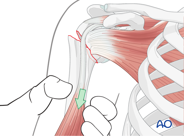
While longitudinal traction is applied to the limb, insert a periosteal elevator into the fracture gap to disimpact the fracture. The elevator should be inserted from the front and pointed medially and superiorly.
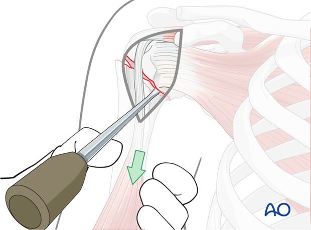
Due to the overlap, the periosteal elevator might not be inserted easily from anterior. If so, insert it into the gap between the fracture fragments. The periosteal elevator might then be used as a lever to disimpact the fragments.
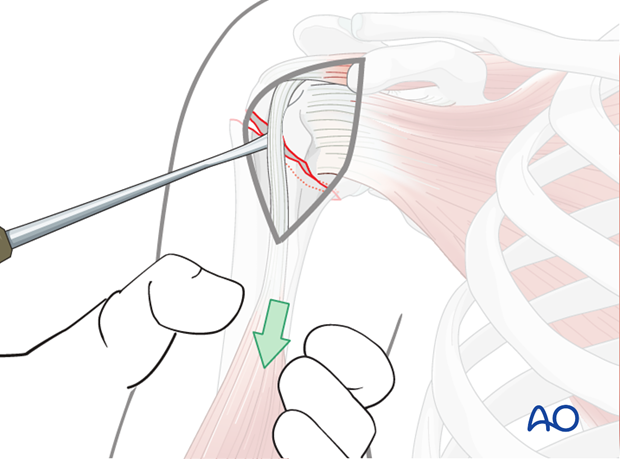
Confirm proper rotational alignment
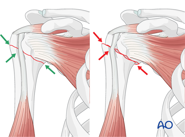
Correct rotational alignment must be confirmed. This can be done by matching the fracture configurations on both sides of the fracture. This would be useful in the more transverse fracture configuration as shown in the illustration.
Pearl: check retroversion
The bicipital groove might be a good indicator for correct rotation. In case of correct rotation, no gap/angulation is visible at the level of the fracture.
In these fractures the combined forces of the tendons are normally neutral, therefore, the humeral head is in neutral version. Remember that the humeral head is normally retroverted, facing approximately 25° posteriorly (mean range: 18°-30°) relative to the distal humeral epicondylar axis. This axis is perpendicular to the forearm with the elbow flexed to 90°.
Preliminary fixation
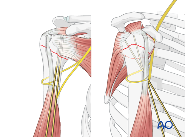
Holding the reduction manually or with a pointed reduction forceps, temporarily secure it with 2 K-wires. Place them outside the foreseen screw position. The illustration shows two such K-wires placed from distal to proximal. Alternatively, they might be inserted from proximal to distal.
Avoid the path of the axillary nerve.
Confirm reduction
The correct reduction must be confirmed in both AP and lateral views by image intensification.
4. Plate position
Correct plate position
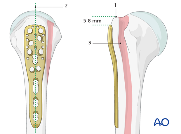
The correct plate position is:
- about 5-8 mm distal to the top of the greater tuberosity
- aligned properly along the axis of the humeral shaft
- slightly posterior to the bicipital groove (2-4 mm)
Confirmation of correct plate position
The correct plate position can be checked by palpation of its relationship to the bony structures and also confirmed by image intensification.
To confirm a correct axial plate position insert a K-wire through the proximal hole of the insertion guide. The K-wire should rest on the top of the humeral head.

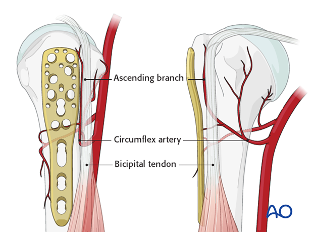
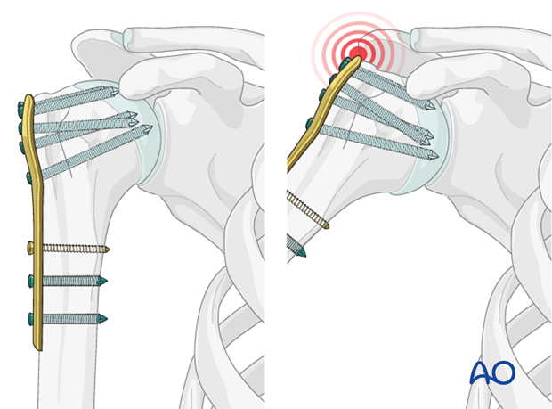
Pitfall 1: plate too close to the bicipital groove
The bicipital tendon and the ascending branch of the anterior humeral circumflex artery are at risk if the plate is positioned too close to the bicipital groove. (The illustration shows the plate in correct position, posterior to the bicipital groove).
Pitfall 2: plate too proximal
A plate positioned too proximal carries two risks:
- The plate can impinge the acromion
- The most proximal screws might penetrate or fail to securely engage the humeral head
5. Fixation
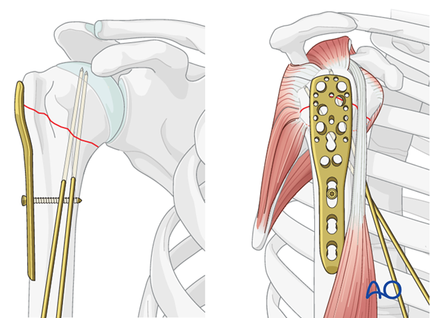
Attach plate to humeral shaft
Attach the plate to the humeral shaft with a bicortical small fragment 3.5 mm screw inserted through the elongated hole.
Pearl 1: fine tuning of plate position
If the first screw is inserted only loosely in the center of the elongated hole, fine-tuning of the plate position is still possible. With the plate in proper position, tighten this screw securely.
Fix plate to the humeral head
Drill holes
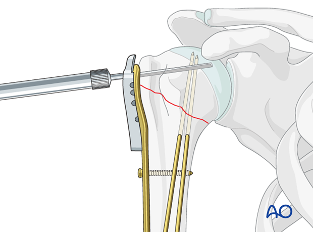
Use an appropriate sleeve to drill holes for the humeral head screws. Do not drill through the subchondral bone and into the shoulder joint.
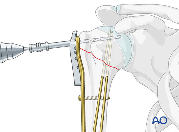
Avoiding intraarticular screw placement
Screws that penetrate the humeral head may significantly damage the glenoid cartilage. Primary penetration occurs when the screws are initially placed. Secondary penetration is the result of subsequent fracture collapse. Drilling into the joint increases the risk of screws becoming intraarticular.
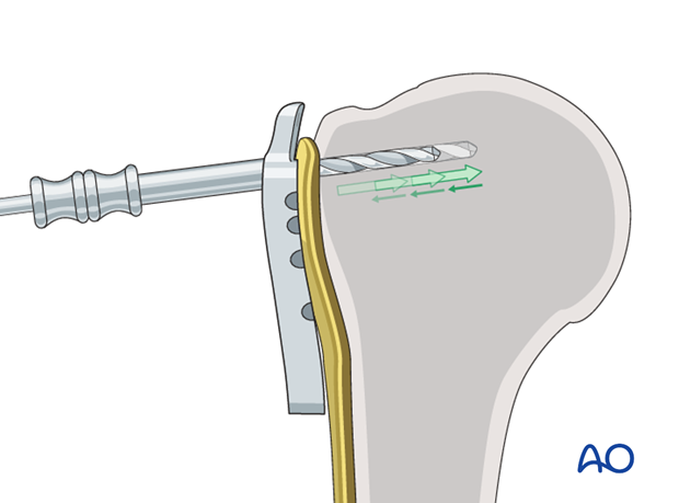
Two drilling techniques help to avoid drilling into the joint.
Pearl 1: “Woodpecker”-drilling technique (as illustrated)
In the woodpecker-drilling technique, advance the drill bit only for a short distance, then pull the drill back before advancing again. Keep repeating this procedure until subchondral bone contact can be felt. Take great care to avoid penetration of the humeral head.
Pearl 2: Drilling near cortex only
Particular in osteoporotic bone, one can drill only through the near cortex. Push the depth gauge through the remaining bone until subchondral resistance is felt.
Determine screw length
The intact subchondral bone should be felt with a depth gauge or blunt pin to ensure that the screw stays within the humeral head. The integrity of the subchondral bone can be confirmed by palpation or the sound of the instrument tapping against it. Typically, choose a screw slightly shorter than the measured length.
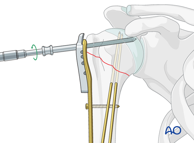
Insert screw
Insert a locking-head screw through the screw sleeve into the humeral head. The sleeve aims the screw correctly. Particularly in osteoporotic bone, a screw may not follow the hole that has been drilled.
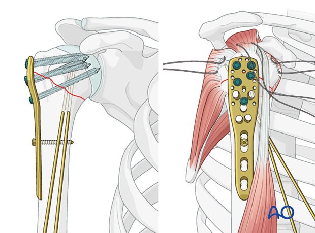
Number of screws and location
Place a sufficient number of screws (often 5) into the humeral head. The optimal number and location of screws has not been determined. Bone quality and fracture morphology should be considered. In osteoporotic bone a higher number of screws may be required.
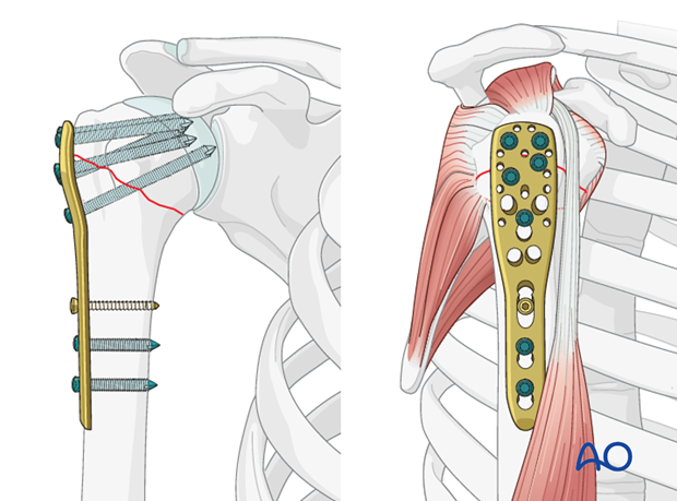
Insert additional screws into the humeral shaft
Insert one or two additional bicortical screws into the humeral shaft.
Any K-wires placed during the procedure may now be removed.
Additional tension band suturing
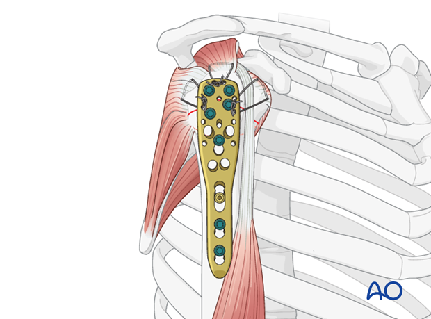
To augment fixation of the plate to the proximal humerus, consider adding tension band sutures through the rotator cuff tendon insertions and appropriate holes in the plate. Resorbable sutures are recommended.
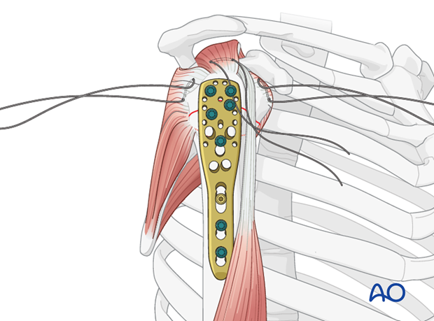
Pass the sutures through the corresponding holes in the plate and tie them together.
Pitfall: insufficient reduction
A common mistake is inadequate reduction. Residual varus malalignment often results in further (secondary) displacement with varus malunion or fixation failure and possible nonunion.
6. Use of standard plates
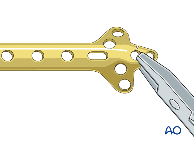
If no angular stable plate is available, a standard plate provides an alternative. The described procedure (reduction, preliminary fixation, and rotator cuff sutures) is essentially the same for standard plates, except for the screws. A good choice from the standard plates is the small fragment cloverleaf plate, with its tip cut off, and contoured as necessary. This plate allows multiple small fragment screws for the humeral head.
Be aware that angular stable implants provide better fixation, especially in osteoporotic bone. On the other hand, even angular stable plates are not a substitute for good surgical technique and judgment. Advances in fracture classification, understanding of the blood supply, use of rotator cuff tendon sutures, anatomical fracture reduction, and provisional fixation, represent improvements in care. When combined with optimal implants, these contributions offer the best chance of a good outcome.
7. Final check of osteosynthesis
Using image intensification, carefully check for correct reduction and fixation (including proper implant position and length) at various arm positions. Ensure that screw tips are not intraarticular.
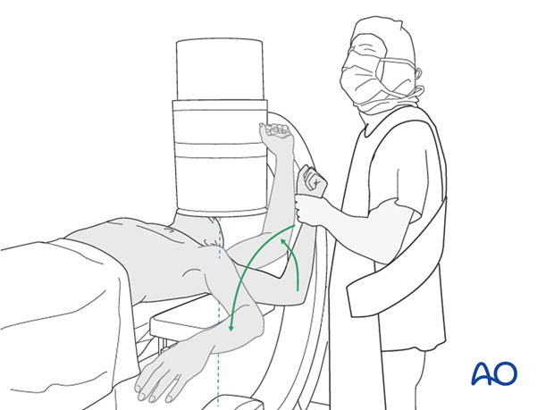
Also obtain an axial view.
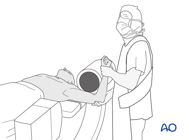
In the beach chair position, the C-arm must be directed appropriately for orthogonal views. Position arm as necessary to confirm that reduction is satisfactory, fixation is stable, and no s


