K-Wire Fixation of Distal Radius Fractures With and Without External Fixation
K-Wire Fixation of Distal Radius Fractures With and Without External Fixation
DEFINITION
■ Distal radius fractures occur at the distal end of the bone, originating in the metaphyseal region and often extending to the radiocarpal and distal radioulnar joints.
■ Distal radius fractures can be classified as stable or unstable and extra- or intra-articular to assist in treatment decisions.
■ Fractures may angulate dorsal or volar and may have signif- icant comminution, depending on the energy of the injury and the quality of the bone.
■ Percutaneous pins or K-wires, typically 0.062- or 0.045- inch, can be used for unstable intra-articular or extra-articular fractures with mild comminution and no osteoporosis.
■ Percutaneous pins can aid reduction and stabilize the frag- ments in a minimally invasive manner.
■ Percutaneous pins can support the subchondral area of the distal radius and maintain the articular reduction in highly comminuted fractures, which is useful in combined fixation methods.
■ Smooth percutaneous pins may also be placed across the physis to maintain a reduction in children without causing a growth arrest.
■ Highly comminuted fractures are more difficult to fix rigidly and often require internal and external fixation to maintain alignment during healing.
■ External fixators can be hinged or static, and may or may not bridge the wrist joint.
ANATOMY
■ The distal radius consists of three articular surfaces: the scaphoid fossa, the lunate fossa, and the sigmoid notch.
■ Ligamentotaxis aids in the reduction of intra-articular and comminuted fractures.
■ Volar ligamentous attachments include the radioscapho- capitate, long radiolunate, and short radiolunate ligaments.
■ Dorsal ligamentous attachments include the dorsal inter- carpal and radiocarpal ligaments.
■ Dorsal and radial to the second metacarpal lie the first dor- sal interosseous muscle and the terminal branches of the radial sensory nerve.
■ The distal radial sensory nerve branches lie superficial to the distal radius and should be protected during dissection and pin placement.
■ The radial sensory nerve emerges between the brachioradi- alis and the extensor carpi radialis longus (ECRL) muscle bellies (FIG 1).
■ The terminal branches of the lateral antebrachial cutaneous
nerve lie superficial to the forearm fascia at the radial wrist.
■ There is a bare spot of bone between the first and second dorsal compartments in the region of the radial styloid.
■ The brachioradialis tendon inserts onto the radial styloid adjacent to the first dorsal compartment.
■ The extensor carpi radialis longus and the extensor carpi ra- dialis brevis lie dorsal to the brachioradialis in the second dor- sal compartment.
■ Lister’s tubercle is dorsal, with the extensor pollicis longus
(EPL) tendon on its ulnar side, in the third dorsal compartment.
■ The extensor digitorum communis tendons lie over the dorsal ulnar half of the distal radius in the fourth dorsal compartment.
■ The extensor digiti minimi lies over the distal radioulnar joint (DRUJ) in the fifth dorsal compartment.
PATHOGENESIS
■ Distal radius fractures are the most common fractures of the upper extremity in adults, representing about 20% of all frac- tures seen in the emergency room.17
■ Mechanism of injury typically is a fall on an outstretched hand with axial loading, but other common histories include motor vehicle accidents or pathologic fractures.
■ Higher-energy injuries cause increased comminution, angu- lation, and displacement.
■ Osteoporosis, tumors, and metabolic bone diseases are risk factors for sustaining pathologic distal radius fractures.
■ In children, fractures typically occur along the physis due to its relative weakness compared to the surrounding ligaments.
NATURAL HISTORY
■ Distal radius fractures needing no reduction and those that are stable after reduction typically recover functional range of motion with minimal long-term sequelae.
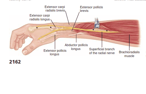
FIG 1 • Anatomy surrounding the radial sensory nerve branch in the forearm.
■ Three parameters that affect outcome include articular con- gruity, angulation, and shortening.16,20
■ 1 to 2 mm of articular surface incongruity of the distal ra- dius can lead to degenerative changes, pain, and stiffness.
■ Dorsal angulation can lead to decreased range of motion and increased load transfer to the ulna.
■ Radial shortening can lead to decreased range of motion, pain, and ulnar impaction of the carpus.
PATIENT HISTORY AND PHYSICAL FINDINGS
■ The history of a fall on an outstretched hand is the most com- mon presentation for a patient with a distal radius fracture.
■ Motor vehicle or motorcycle accidents and osteoporosis ac- count for most comminuted fractures.
■ It may be clinically indicated to implement a workup for osteoporosis.
■ Pain, tenderness, swelling, crepitus, deformity, ecchymosis, and decreased range of motion at the wrist are typical symp- toms and warrant radiographic evaluation.
■ Physical examination should include the following:
■ Inspection: Evaluate the integrity of the skin, cascade of the digits, direction of displacement, and presence of any swelling.
■ Identify points of maximal tenderness to differentiate be- tween distal radius injuries and carpal or ligamentous injuries.
■ Touch or press specific areas of the wrist and hand to dif- ferentiate distal intra-articular, DRUJ, and carpal injuries.
■ Two-point discrimination: Higher than normal (5 mm) results in the form of progressive neurologic deficit may sig- nify an acute carpal tunnel syndrome or ulnar neuropathy.
■ Passive finger stretch test to assist with diagnosis of com- partment syndrome.
■ EPL tendon function should be evaluated.
■ EPL assessment: Assess the resting position of the thumb interphalangeal joint and the patient’s ability to lift the thumb off of a flat surface to determine the continuity of the EPL tendon.
■ Palpation of forearm and elbow to assess for concomitant injury proximally.
■ The DRUJ must be assessed for displacement.
■ The bony anatomy must be carefully evaluated to avoid missing minimally displaced fractures, which may displace without treatment.
■ Skin should be assessed to avoid missing an open fracture.
■ Swelling should be monitored to allow for early diagnosis of compartment syndrome.
■ Sensory examination should be monitored for progressive changes, which may represent acute carpal tunnel syndrome.
IMAGING AND OTHER DIAGNOSTIC STUDIES
■ Radiographic evaluation should include posteroanterior (PA), lateral, and oblique views to assess displacement, angu- lation, comminution, and intra-articular involvement, and allow for radiologic measurements.14,17
■ Lateral articular (volar) tilt is the angle between the radial shaft and a tangential line parallel to the articular margin as seen on the lateral view (FIG 2A). The normal angle is
11 degrees.
■ Radial inclination, measured on the PA view (FIG 2B), is the angle between a line perpendicular to the shaft of the radius at the ulnar articular margin and the tangential line
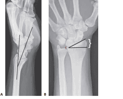
FIG 2 • A. Lateral radiograph of the wrist demonstrating volar tilt (black lines). B. PA radiograph demonstrating radial incli- nation (black lines), ulnar variance (red bracket), and radial height (white bracket).
along the radial styloid to the ulnar articular margin. The normal angle is 22 degrees.
■ Ulnar variance, also measured on the PA view (see Fig 2B), is the distance between the radial and ulnar articular surfaces. Ulnar variance is compared to the contralateral side.
■ Traction radiographs help assess intra-articular involve- ment, intercarpal ligamentous injury, and potential fracture re- duction through ligamentotaxis.
■ CT scans are useful in fully elucidating the anatomy of the fracture, including impaction, comminution, and size of the fragments.
■ CT scans often significantly alter the original treatment plan.11
■ MRI is rarely performed acutely but can diagnose concomi- tant ligamentous injuries, triangular fibrocartilage complex in- juries, and occult carpal fractures.
DIFFERENTIAL DIAGNOSIS
■ Bony contusion
■ Radiocarpal dislocation
■ Scaphoid or other carpal fracture
■ Perilunate or lunate fracture dislocation
■ Distal ulna fracture
■ Wrist ligament or triangular fibrocartilage complex injury
■ DRUJ injury
NONOPERATIVE MANAGEMENT
■ Conservative treatment consists of splinting or casting for stable fracture patterns using a three-point mold.
■ Fractures amenable to nonoperative treatment include frac- tures that are stable after reduction with minimal metaphyseal comminution, shortening, angulation, and displacement.
■ Evaluation for secondary displacement weekly for 2 to
3 weeks is critical as the swelling subsides.
■ Unstable patterns will displace if not surgically stabilized.
■ There is little role for nonoperative treatment in highly comminuted fractures.
■ The physiologic age, medical comorbidities, and functional level of the patient should be considered in determining the need for surgical treatment.
■ Early range of motion of the nonimmobilized joints is essen- tial in the nonoperative treatment of all fractures near the wrist to prevent contracture.
■ The cast or splint must not extend past the metacar- pophalangeal joints so as to allow digital motion.
SURGICAL MANAGEMENT
■ Surgical treatments are indicated to prevent malunion and improve pain control, function, and range of motion.
■ Surgery is reserved for unstable fractures, including dis- placed, intra-articular, comminuted, or severely angulated in- juries and fractures that displace following attempted closed management.
■ Percutaneous pinning can assist in obtaining and maintain- ing reduction of displaced fractures with limited comminution in a minimally invasive manner.
■ External fixators maintain radius length but cannot always control angulation and displacement; therefore, supplementa- tion with percutaneous pins is typically performed.2
■ Conversely, external fixators may augment percutaneous pins and plate fixation when extensive comminution is present.
■ Supplemental external fixation should be considered for fractures with comminution of over 50% of the diameter of the radius on a lateral view.
■ External fixation may be used as a neutralization device, because the distraction forces decrease soon after fracture reduction.
■ External fixators also are useful for “damage control or- thopaedics” to temporarily stabilize wrist fractures, especially for complex, combined, open injuries.
■ For nonbridging external fixation, there must be at least
1 cm of volar cortex intact and adequate fragment sizes to allow proper pin placement.
■ A relative contraindication to pin fixation with or without external fixation is a volar shear injury, which should be re- duced and stabilized using a volar plate and screws.
Preoperative Planning
■ All radiographs should be reviewed before surgery and brought into the operating room.
■ Analysis of the pattern and presumed stability of the frac- ture fragments determines whether percutaneous fixation, with or without external fixation, is suitable.
■ For intra-articular fractures, the specific fragments to be re- duced and fixed must be identified preoperatively to avoid in- complete reduction of the joint surface.
■ The surgeon must be prepared to change his or her manage- ment decision intraoperatively if the fracture behavior is differ- ent than anticipated. A variety of fixation devices should be available in the operating room.
Positioning
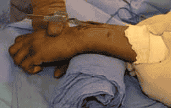
■ The patient is positioned supine on the operating table with a radiolucent arm board.
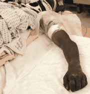
FIG 3 • Positioning of patient supine on the hand table with tourniquet in place.
■ A tourniquet is applied near the axilla with the splint still in place (FIG 3).
■ Fluoroscopy should be used for reduction confirmation and
fixation throughout the procedure.
■ There must be enough range of motion of the shoulder and elbow to allow standard AP, lateral, and oblique images.
Approach
■ Various approaches can be used in the application of exter- nal fixators and the insertion of percutaneous pins.
■ Distal external fixator half-pins may be placed directly into the second metacarpal or into other carpal bones (for injuries in- cluding the second metacarpal). Wires and half-pins, which are non-bridging fixators, may be placed in the distal radius itself.
■ Percutaneous pins can be inserted through the radial styloid between the first and second dorsal compartments, through Lister’s tubercle, through the interval between the fourth and fifth dorsal compartments, and across the DRUJ (FIG 4).
■ Caution is taken to avoid skewering tendons and nerves
and to avoid penetrating the articular surface.
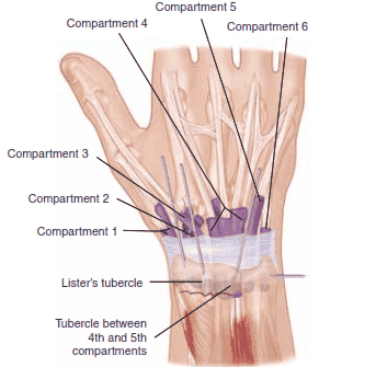
FIG 4 • Areas for K-wire insertion at the distal radius.
CLOSED REDUCTION OF A DISTAL RADIUS FRACTURE
■ Closed reduction should be performed before fixation using distraction and palmar translation of the distal ra- dius fragment and carpus.1
■ Use of a padded bump or towel roll will aid in the reduc-
tion (TECH FIG 1).
■ Overdistraction will cause increased dorsal angulation due to the intact short, stout volar ligaments.1
■ Excessive palmar flexion of the wrist can restore volar tilt
but leads to an increased incidence of stiffness and carpal tunnel syndrome.7
■ Overdistraction can be assessed by measuring the carpal
height index, measuring the radioscaphoid and midcarpal joint spaces, checking full finger flexion into the palm, or evaluating index finger extrinsic extensor tightness.8
TECH FIG 1 • Closed reduction over a towel bump using trac- tion and palmar translation.
KAPANDJI TECHNIQUE FOR PERCUTANEOUS PINNING
■ Closed reduction is obtained using a bump, and the re- duction is confirmed using fluoroscopy.
■ This technique should be employed in patients younger
than 55 years of age with minimal comminution. It should not be used in osteoporotic, elderly patients or those with comminution secondary to a higher loss of reduc- tion. External fixation should be used to supplement pin- ning in these populations.21
■ A stab incision is made radially, and a 0.062-inch pin is manually inserted into the fracture site, taking care to protect the sensory nerve branches and the first dor- sal compartment tendons (TECH FIG 2A).
■ The pin is angled distal, levering the bone back into
its normal position and restoring the radial inclina- tion (TECH FIG 2B). The pin is advanced through the far cortex using power, acting as a buttress to prevent loss of radial inclination (TECH FIG 2C).
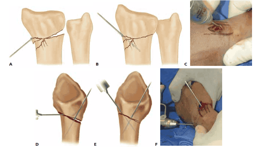
TECH FIG 2 • A. An incision is made over the radial styloid and a K-wire is manually inserted into the fracture site. B. The wire is levered distally to correct the radial inclination. C. The wire is advanced proximally, using power, into cortical bone. D. An incision is made over Lister’s tubercle, and a wire is inserted into the fracture site. E,F. The wire is levered distally to correct the dorsal angulation and advanced proximally using power into cortical bone.
■ A second stab incision is placed dorsally, and a second pin is manually inserted into the fracture (TECH FIG 2D).
■ The pin is angled distal, levering the bone back into
its normal position and restoring the volar tilt (TECH FIG 2E). The pin is advanced through the volar cortex using power, acting as a buttress to prevent loss of volar tilt (TECH FIG 2F).
■ Using the modified technique, a third pin is placed retro-
grade using power, starting at the radial styloid and pro-
ceeding into the ulnar cortex of the radius proximal to the fracture line.
■ The pins are buried and cut just below the skin, and the
skin is sutured.
■ Alternatively, the pins may be bent using two needle drivers and left outside the skin.
■ The pins are then cut and covered with pin caps or antibi-
otic gauze.
■ A sterile dressing is applied, followed by a splint.
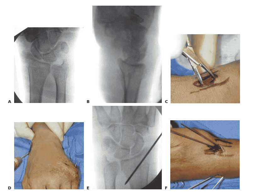
AUTHOR’S PREFERRED TECHNIQUE FOR PERCUTANEOUS PINNING
■ Closed reduction is obtained using a bump, and the re- duction is confirmed using fluoroscopy (TECH FIG 3A,B).
■ A small incision is placed over the bare spot on the radial
styloid between the first and second dorsal compart- ments (TECH FIG 3C).
■ Two 0.062-inch smooth K-wires are placed retrograde
from the radial styloid across the reduced fracture, en- gaging the opposite cortex in a divergent fashion (TECH FIG 3D,E).
■ A small incision is placed over the interval between the
fourth and fifth dorsal compartments.
■ One or two K-wires are placed retrograde from the dor- sal ulnar corner of the distal radius across the reduced fracture, engaging the opposite cortex in a divergent fashion (TECH FIG 3F–H).
■ The pins are cut just beneath the skin, which is closed
with a 5-0 nylon suture.
■ Alternatively, the pins are bent and cut and left outside the skin (TECH FIG 3I).
■ A dressing and splint are then applied.