
RADIAL STYLOID FRACTURES
RADIAL STYLOID FRACTURES
■ An isolated fracture of the radial styloid is an ideal fracture pattern to manage arthroscopically, especially for the surgeon beginning to gain experience in arthroscopeassisted fixation of distal radius fractures.
■ In addition, radial styloid fractures have a high incidence
of associated injury to the scapholunate interosseous ligament, which is best assessed arthroscopically.
■ Insert one or two guidewires from a cannulated screw
system percutaneously into the radial styloid—not across the fracture site—using a wire driver in oscillation mode.
■ Evaluate the position of the wires under fluoroscopy
to ensure they are centered in the radial styloid fragment.
■ Suspend the wrist in a traction tower and establish the
standard arthroscopic portals.
■ Insert the scope in the dorsal 3/4 portal and clear the joint of debris and hematoma.
■ Transfer the arthroscope to the 6R or 4/5 portal to look
across the wrist and effectively judge rotation and reduction of the radial styloid fragment.
■ Using the previously placed guidewires as joysticks, manipulate and anatomically reduce the fracture fragment under direct arthroscopic observation.
■ A trocar can be inserted through the 3/4 portal to
help further guide the reduction of the radial styloid fragment (TECH FIG 1A,B).
■ Once the fracture is judged to be absolutely anatomic,
the guidewires are advanced across the fracture site into the radius shaft and evaluated under fluoroscopy (TECH FIG 1C).
■ In many cases, the fracture reduction may look
anatomic under fluoroscopy, but when viewed arthroscopically, the radial styloid fragment is seen to be slightly rotated.3
■ Guidewires alone can be used to stabilize the fracture,
but cannulated screws (with or without heads) are recommended (TECH FIG 1D,E).
■ Cannulated screws decrease soft tissue irritation and
potential pin track infection as compared with Kwires.
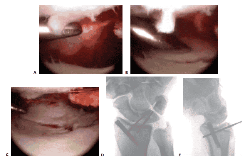
TECH FIG 1 • A. Arthroscopic view of the patient whose radiographs are seen in Figure 1. The arthroscope is in the 6R portal looking across the wrist, and a blunt trochar is in the 3/4 portal. The displaced radial styloid fragment is well visualized. B. A combination of joysticks inserted into the radial styloid fragment and a trochar inserted into the 3/4 portal allows anatomic reduction of the displaced radial styloid fragment and radiocarpal joint. C. The radial styloid fragment is anatomically reduced (with no residual rotation) and stabilized. D. PA view demonstrating anatomic reduction to the radial styloid fragment. Headless cannulated screws are used, if possible, to avoid soft tissue irritation. E. Lateral view showing anatomic restoration to the radial styloid fragment and restoration of the carpus in line with the radius.
THREE-PART FRACTURES
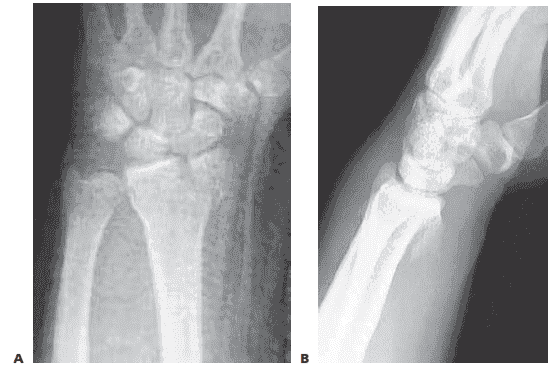
■ Three-part fractures that involve a displaced fracture of the radial styloid and a lunate facet fragment without metaphyseal communution are ideal for arthroscopic-assisted reduction (TECH FIG 2A,B).
■ Reduce and provisionally stabilize the radial
styloid fragment with guidewires under fluoroscopic guidance.
■ The radial styloid serves as a landmark to which the
depressed lunate facet fragment is reduced.
■ Suspend the wrist in the traction tower, establish portals, and evacuate the fracture debris and hematoma.
■ The depressed lunate facet fragment is best seen with
the arthroscope in the 3/4 portal (TECH FIG 2C,D).
■ Percutaneously place a no. 18 needle directly over the depressed fragment as viewed arthroscopically.
■ Insert a large K-wire about 2 cm proximal to the previ-
ously placed no. 18 needle to percutaneously elevate the depressed lunate facet fragment.
■ Use a bone tenaculum to further diminish the gap between the radial styloid and lunate facet fragments.
■ Place guidewires transversely under the subchondral sur-
face of the radius from the radial styloid into the anatomically reduced lunate facet fragment.
■ It is important to pronate and supinate the wrist fol-
lowing placement of the transverse pins to ensure the guidewires have not violated the DRUJ. The concave nature of the DRUJ makes radiographic assessment difficult.
■ Consider insertion of bone graft to support the reduced
lunate fragment and avoid late settling.
■ Make a small incision between the fourth and fifth dorsal compartments.
■ Use cancellous allograft bone chips or bone substitutes.
■ If feasible, place headless cannulated screws to stabilize both the radial styloid and the impacted lunate facet fragments (TECH FIG 2E–H).
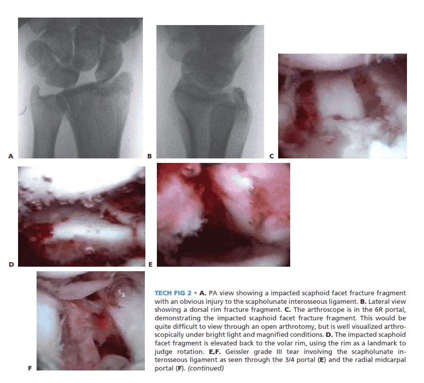
TECH FIG 2 • A. PA view showing a impacted scaphoid facet fracture fragment with an obvious injury to the scapholunate interosseous ligament. B. Lateral view showing a dorsal rim fracture fragment. C. The arthroscope is in the 6R portal, demonstrating the impacted scaphoid facet fracture fragment. This would be quite difficult to view through an open arthrotomy, but is well visualized arthroscopically under bright light and magnified conditions. D. The impacted scaphoid facet fragment is elevated back to the volar rim, using the rim as a landmark to judge rotation. E,F. Geissler grade III tear involving the scapholunate interosseous ligament as seen through the 3/4 portal (E) and the radial midcarpal
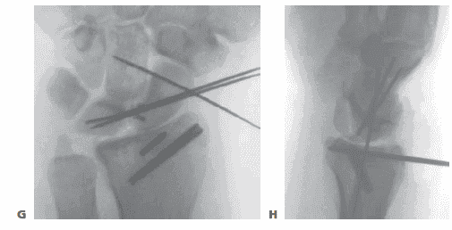
TECH FIG 2 • (continued) G,H. PA and lateral radiographs showing anatomic reduction to the impacted scaphoid facet fracture. (The tear of the scapholunate interosseous ligament also was
THREEAND FOUR-PART FRACTURES WITH METAPHYSEAL COMMINUTION
■ A combination of open surgery, using a volar plate for stability, and arthroscopy, as an adjunct to assist the articular reduction, is used if metaphyseal comminution is present (TECH FIG 3).
■ Volar plate stabilization is very stable and allows for
early range of motion and rehabilitation as compared to
K-wires or headless screws alone.
Open Reduction and Stabilization
■ Perform a standard volar approach and do not open the radiocarpal joint capsule (TECH FIG 4A).
■ The radial styloid fragment and the volar ulnar fragment
are reduced to the shaft under direct visualization. The radial styloid fragment is provisionally pinned.
■ Apply a volar distal radius locking plate to stabilize the
volar bone fragments (TECH FIG 4B).
■ Place a screw in the proximal portion of the plate first, to reduce the plate to the shaft.
■ Provisionally pin the distal fragments through the plate.
■ Manipulate the articular fragments under fluoroscopy to
obtain as anatomic a reduction as possible (TECH FIG
4C,D).
■ Suspend the wrist in the traction tower and reduce the articular fragments arthroscopically (TECH FIG 4E,F).
■ If articular reduction is not anatomic, remove the pins
and fine-tune the reduction.
■ Once the fracture reduction is thought to be anatomic, place the distal screws through the plate (TECH FIG 4G–I).
■ It is important that the fracture be reduced to the
plate, with no gap between the plate and the bone. This can be achieved by flexion of the wrist in the tower and by insertion of a non-locking screw first, before the insertion of standard locking screws.
■ Place the remaining proximal and distal screws if the
reduction is anatomic under both fluoroscopy and arthroscopy.
TECH FIG 3 • A. The PA radiograph shows a displaced fracture of the radial styloid. B. This lateral radiograph shows metaphyseal comminution associated with the displaced radial styloid fragment. Because of the metaphyseal comminution, it was decided to stabilize thefracture using a volar plate
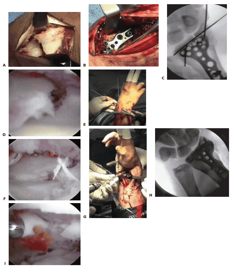 .
.TECH FIG 4 • A. A standard volar approach is made, centered over the flexor carpi radialis tendon, and the fracture site is exposed. B. A volar distal radius locking plate (Acumed, Hillsboro, OR) is applied. The initial screw is placed through the proximal plate to secure the plate to the shaft. C. The intra-articular reduction is viewed under fluoroscopy and provisionally pinned. A displaced intra-articular fracture fragment can still be identified. D. The arthroscope is in the 3/4 portal, showing the volar capsule blocking reduction of the radial styloid fragment. E. Joysticks previously inserted into the radial styloid fragment are then used to control and anatomically reduce the radial styloid fragment. F. The arthroscope is in the 6R portal looking across the wrist. Anatomic reduction of the radial styloid fragment is documented. G. Once the anatomic restoration of the articular surface is evaluated both arthroscopically and fluoroscopically, the distal screws are placed in the plate. H. Fluoroscopic view showing anatomic restoration to the articular surface of the distal radius. I. The patient had an associated osteochondral fracture of the lunate, not visible on plain radiographs. The displaced fragment is arthroscopically removed.
Reduction and Stabilization of a Dorsal Die Punch Fragment
■ It is not possible to see the reduction of a dorsal die punch fragment through the volar approach when stabilized with a plate. Arthroscopy can be helpful in this scenario.
■ Insert the volar plate as previously described and provi-
sionally fix the device to the radius.
■ Frequently, the dorsal fragment may still be slightly proximal in relation to the radial shaft.
■ The dorsal die punch fragment is best seen with the arthroscope in the 6R portal.
■ Establish the volar radial portal between the ra-
dioscaphocapitate ligament and the long radiolunate ligment, as viewed directly through the previous performed volar approach.16
■ Percutaneously elevate and anatomically reduce the dor-
sal die punch fragment as viewed arthroscopically.
■ Once this has been achieved, place the screws into the plate and observe their path arthroscopically to ensure adequate stabilization of the dorsal die punch fragment.